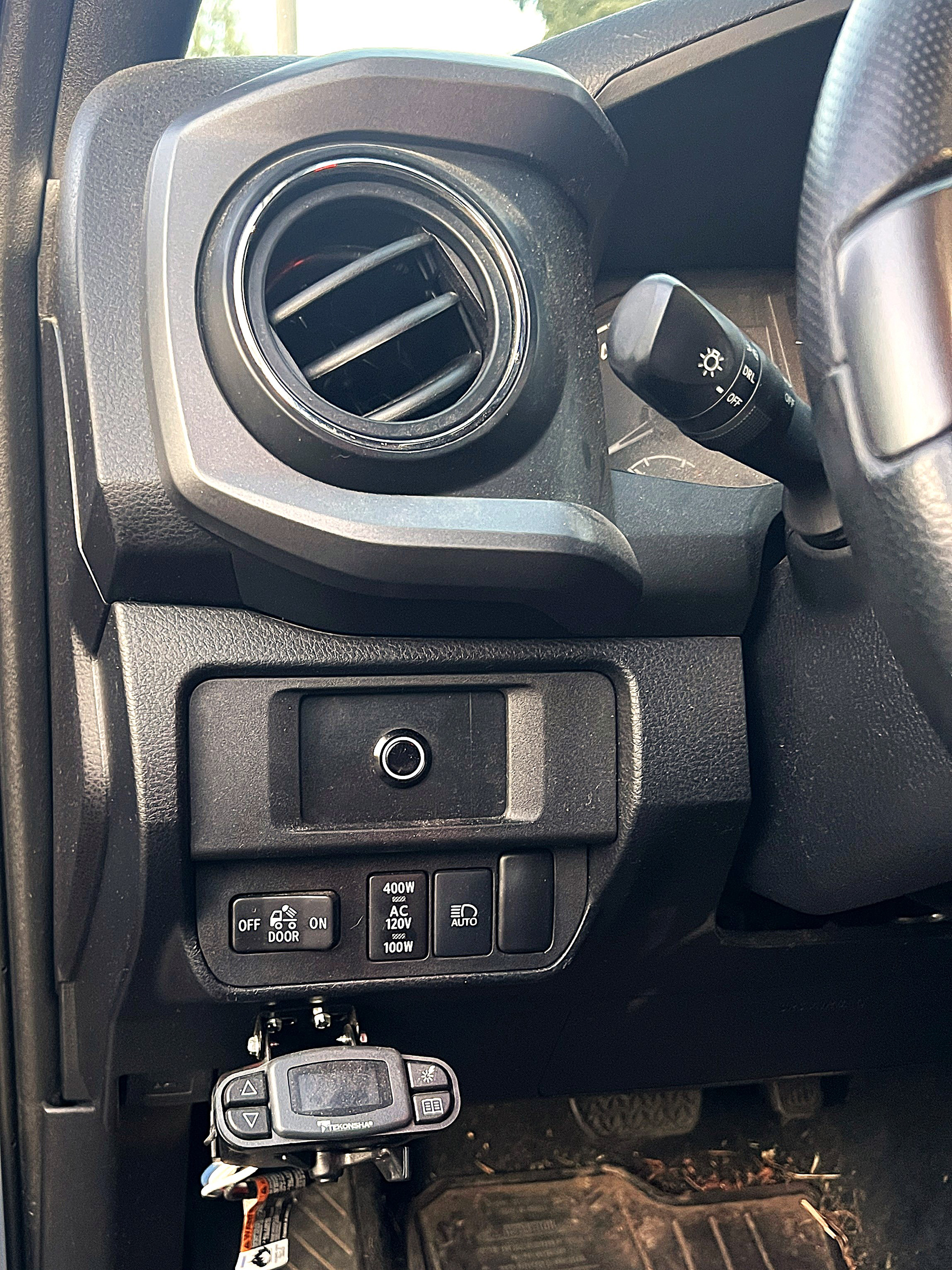
The original switch panel that comes in the 3rd generation Toyota Tacoma is limited in capacity for the amount of switches you can have to manage accessories. I wanted to add switches for ditch lights, an LED light bar, and master power to my 10k winch.
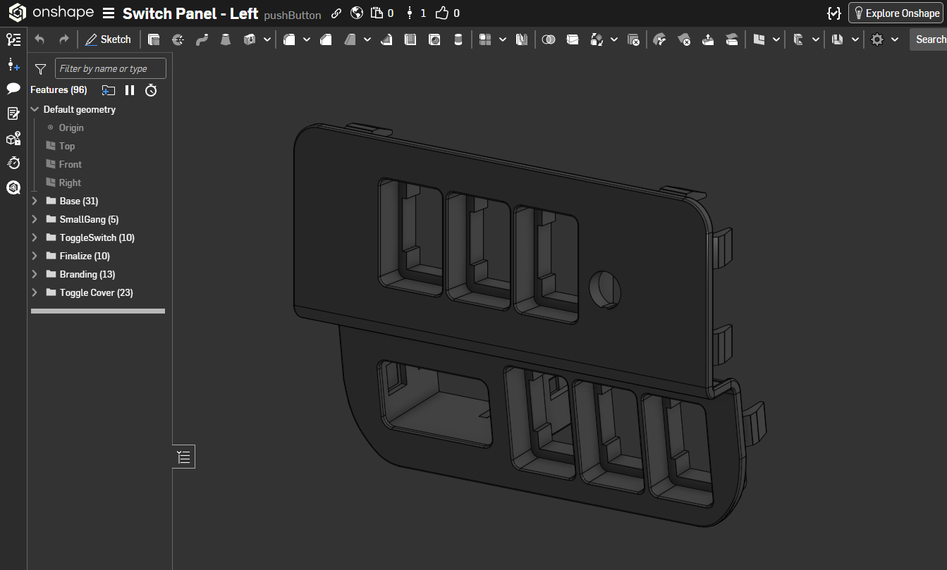
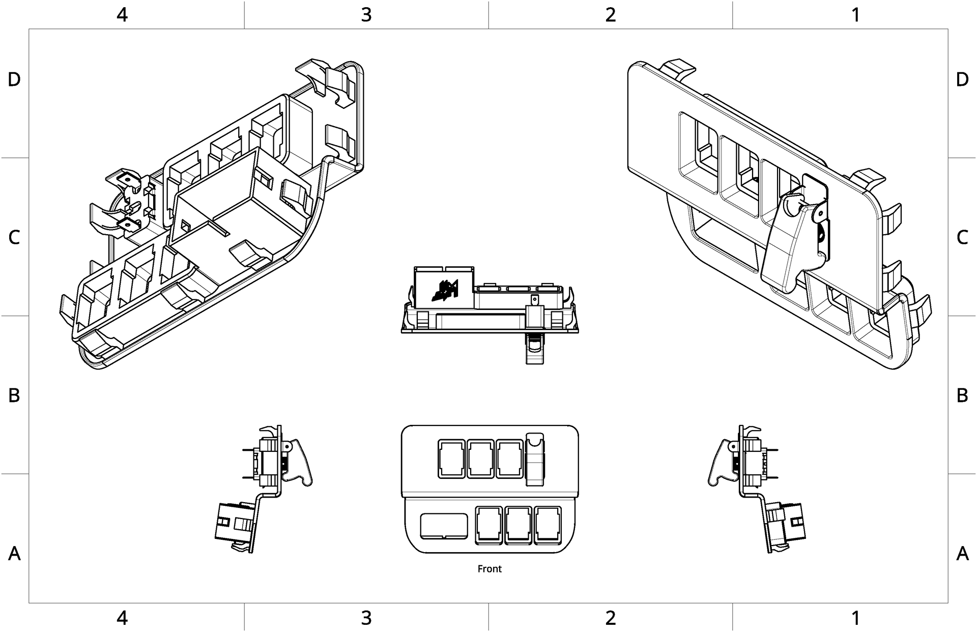
I started by removing the old switch panel and 3D scanning it. This gave me the core geometry to start building from. Using Onshape, I modeled the switch panel and started placing different switch styles to see how many I could fit within the existing panel.
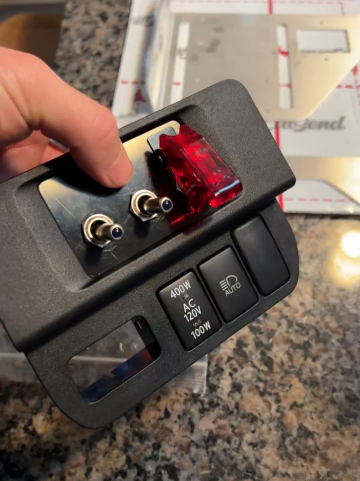
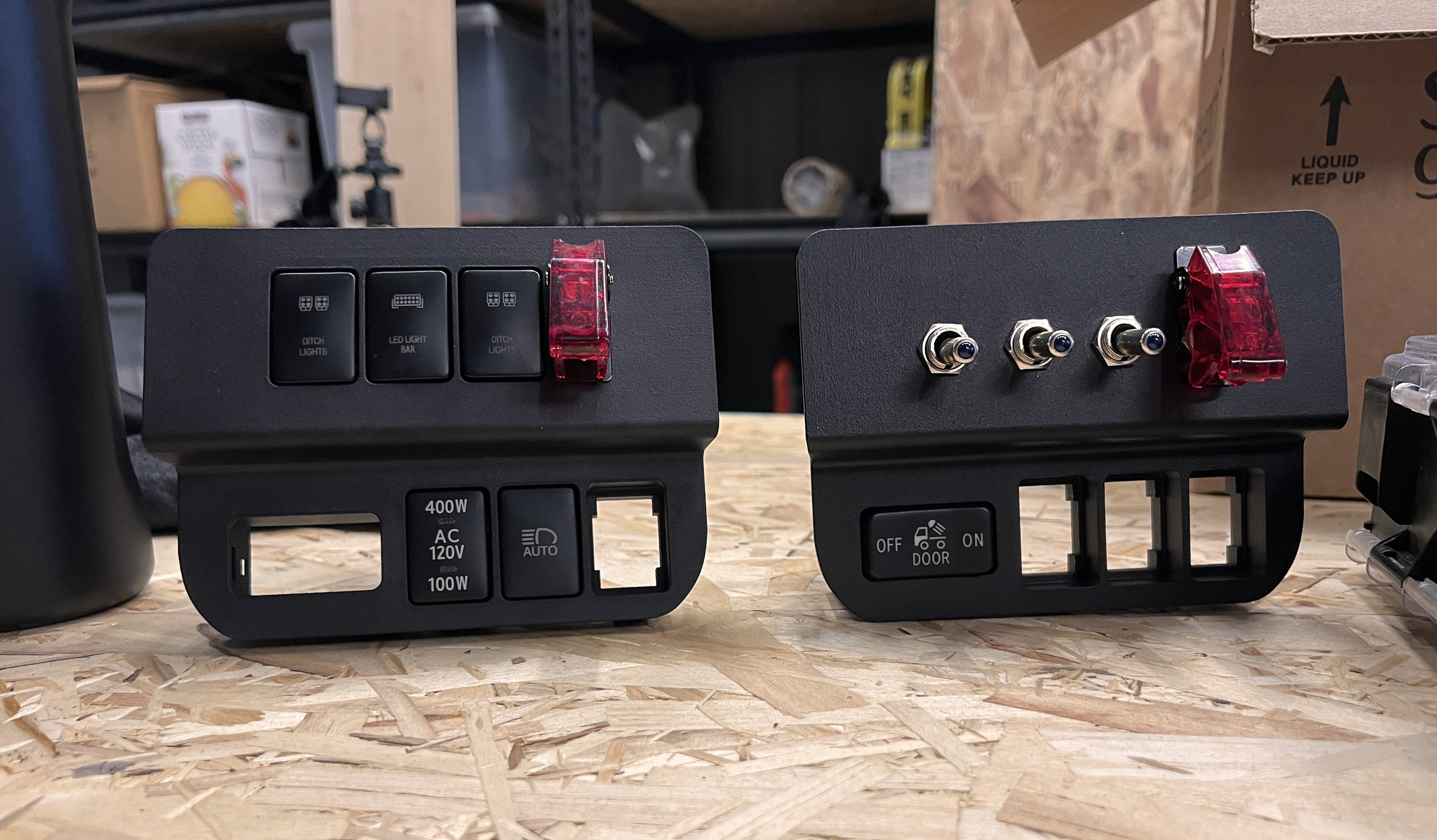
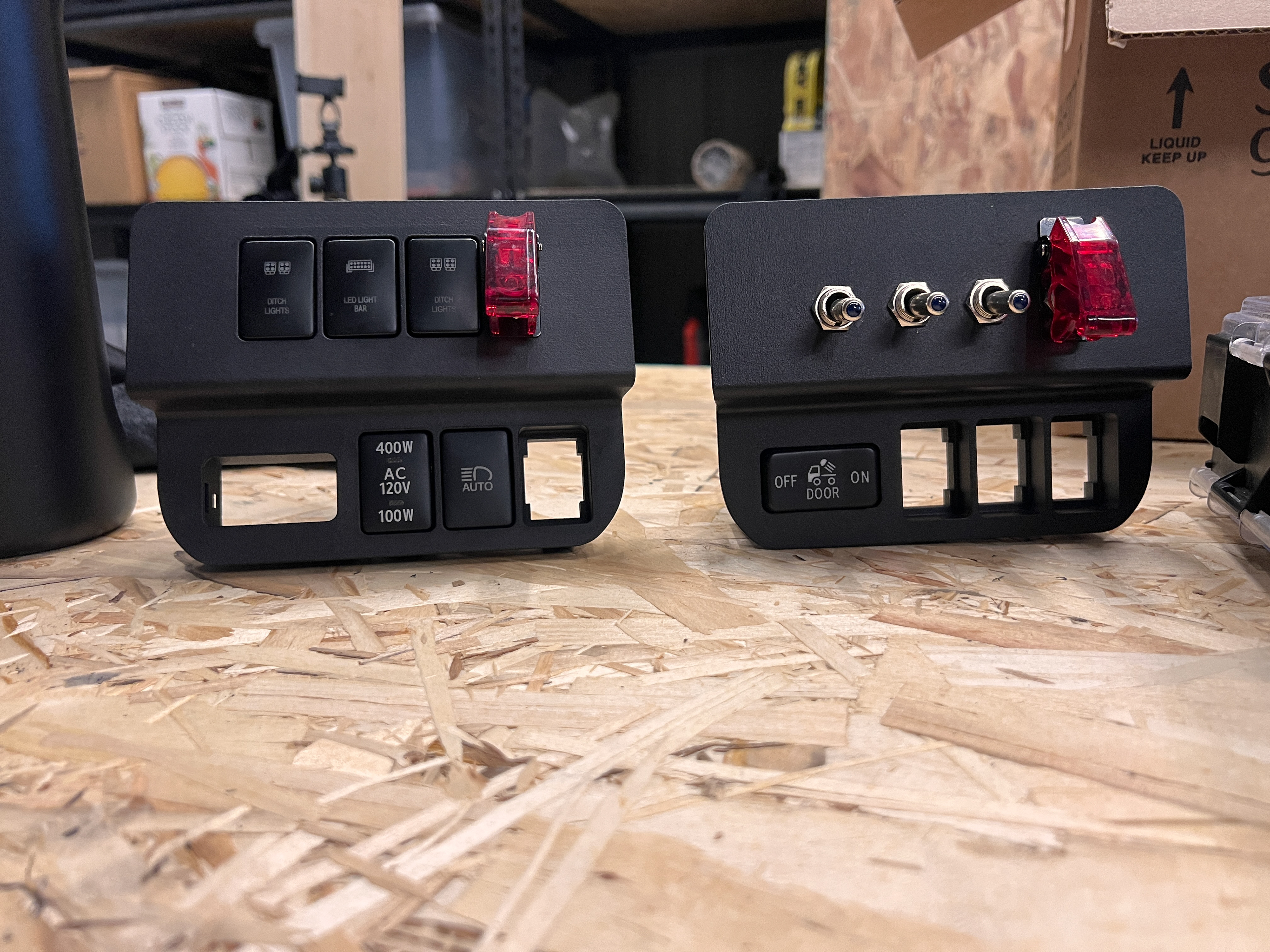
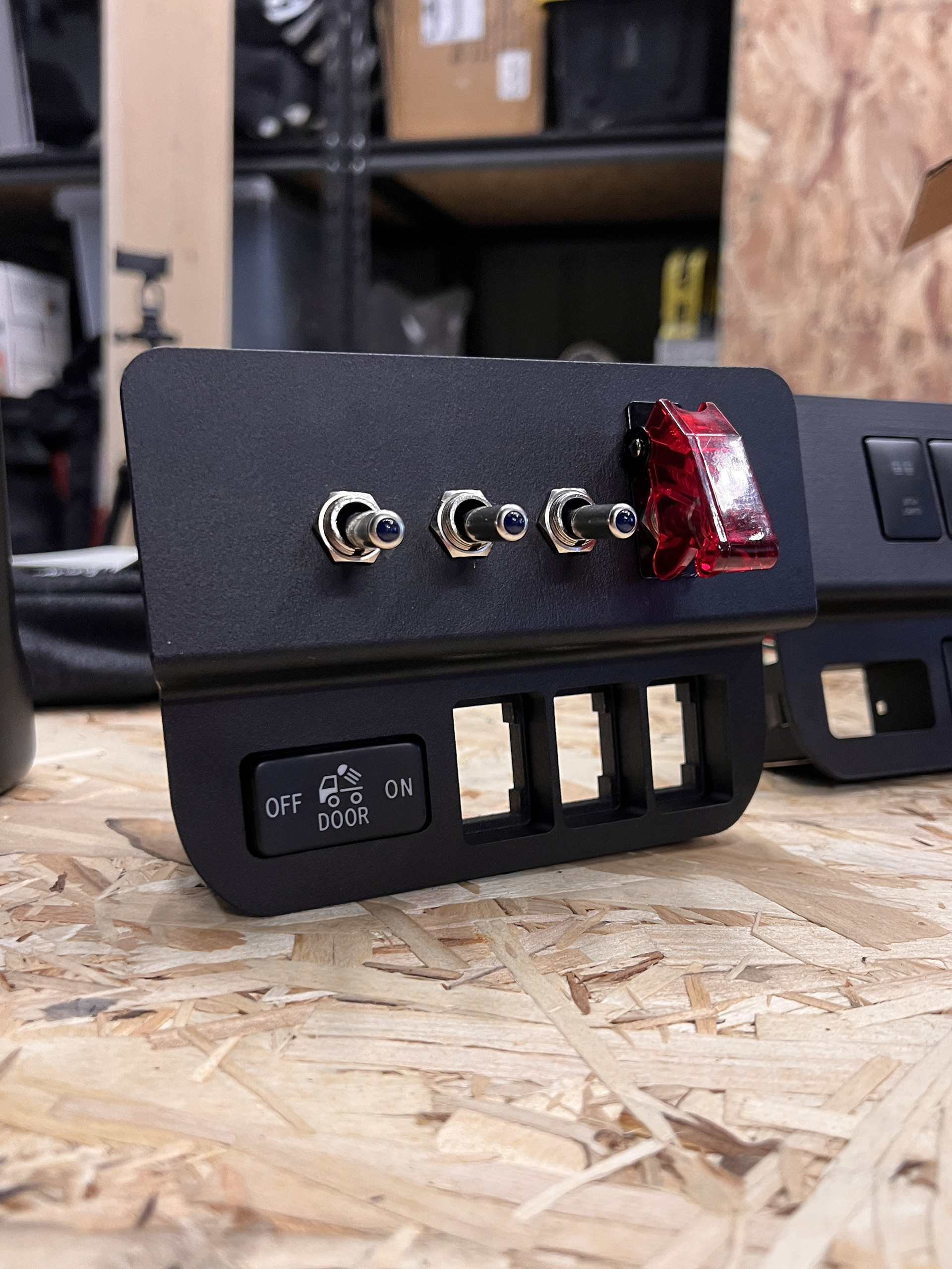
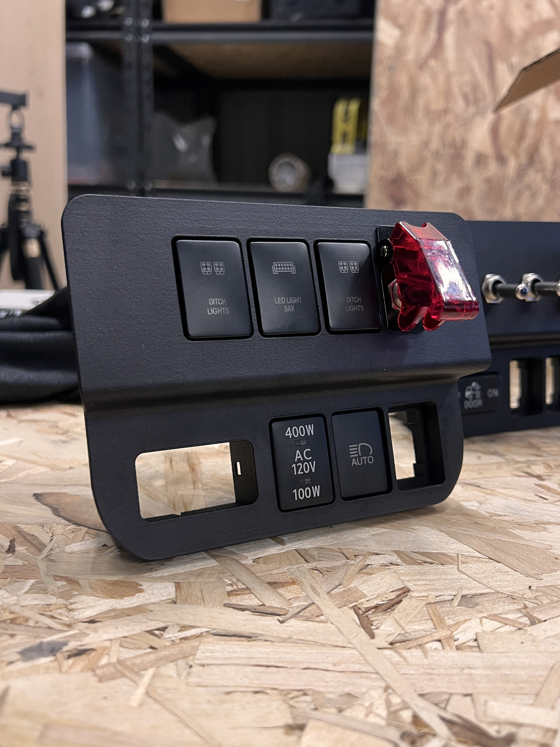
As for design, I wanted to keep this as OEM as possible. I tested two switch styles for the design. I knew I wanted to be very intentional with the winch power, so there is no confusion of whether there is power to the winch or not. That was a non-negotiable from the start.
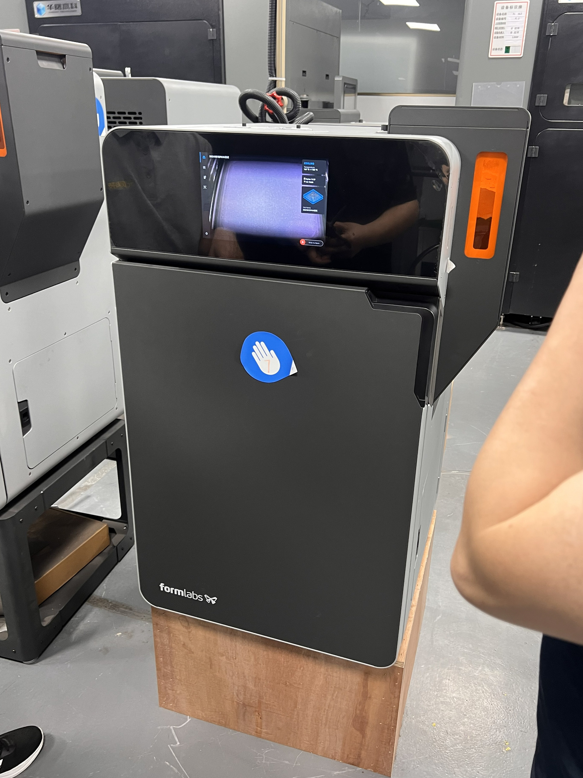
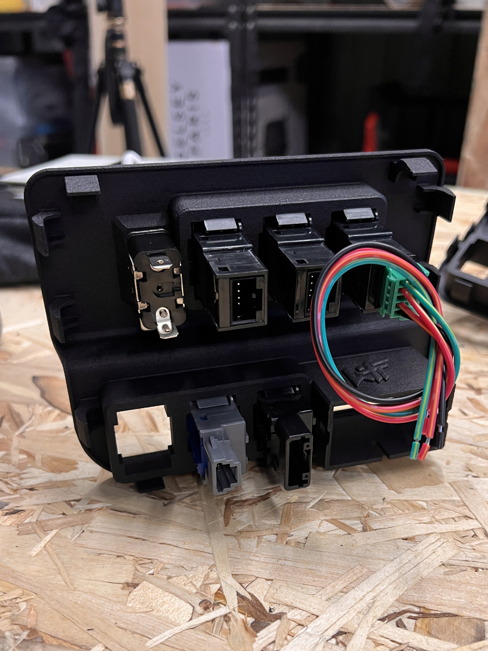
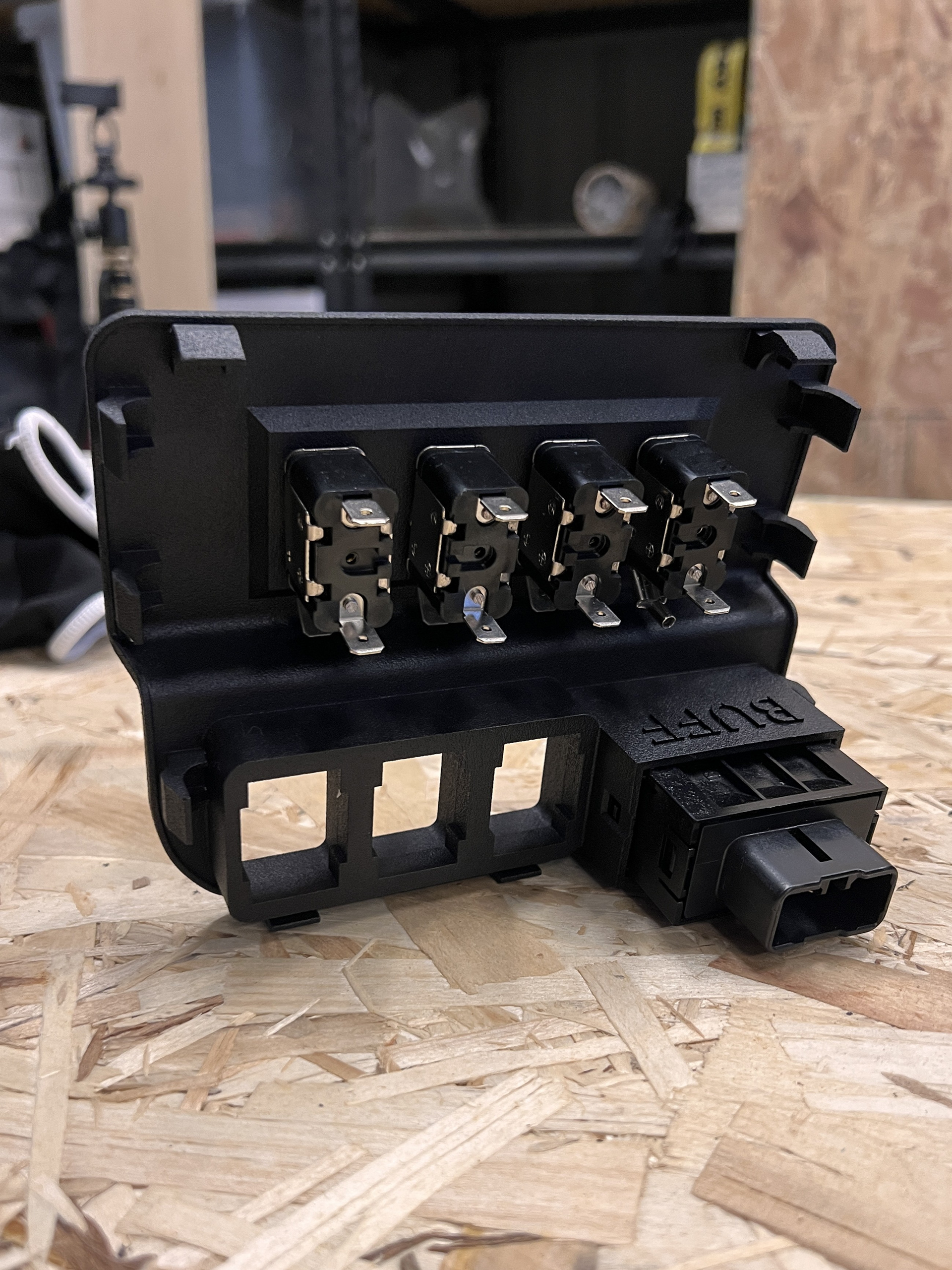
Once I was ready to test my two switch layouts I had the panels printed in Nylon using SLS (selective laser sintering). When I received them I installed the switches and compared the two. It was obvious to me that the standard rocker switch was the direction I wanted to go.
I have a deep interest in electronics. So when installing my switch panel into my dash, the idea of running low current power lines to my engine bay drove me crazy.
I also plan to run an air compressor in the bed of my truck to manage air pressure in my rear airbags, so creating a local wireless network that allows me to inflate/deflate my airbags from the cab (where it matters) is going to be a huge benefit.
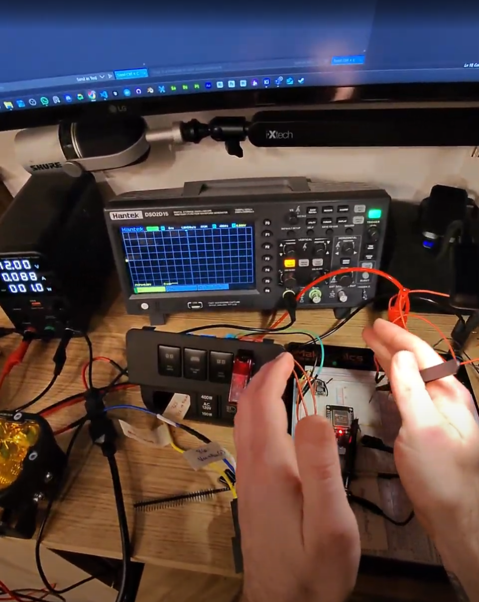
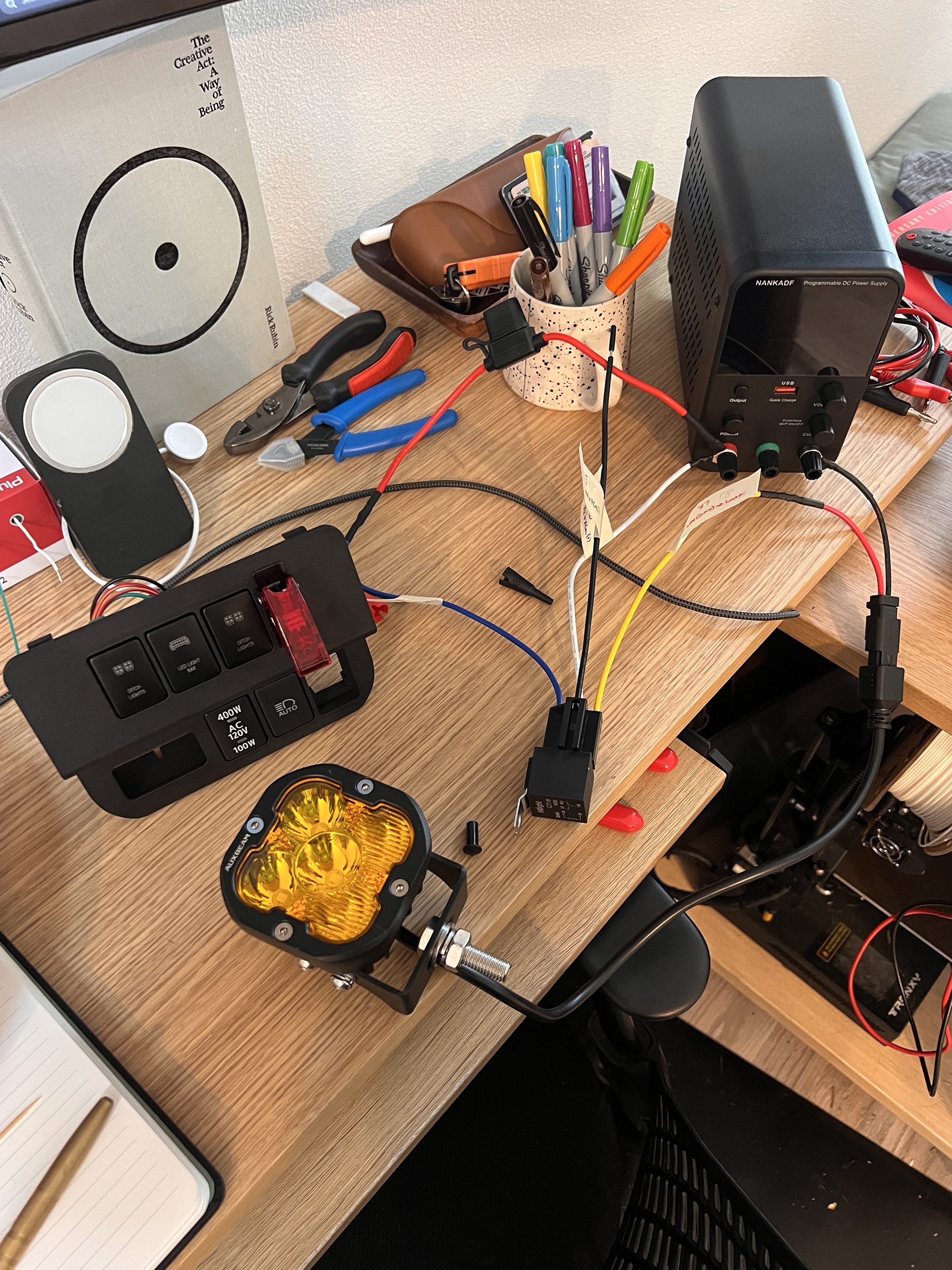
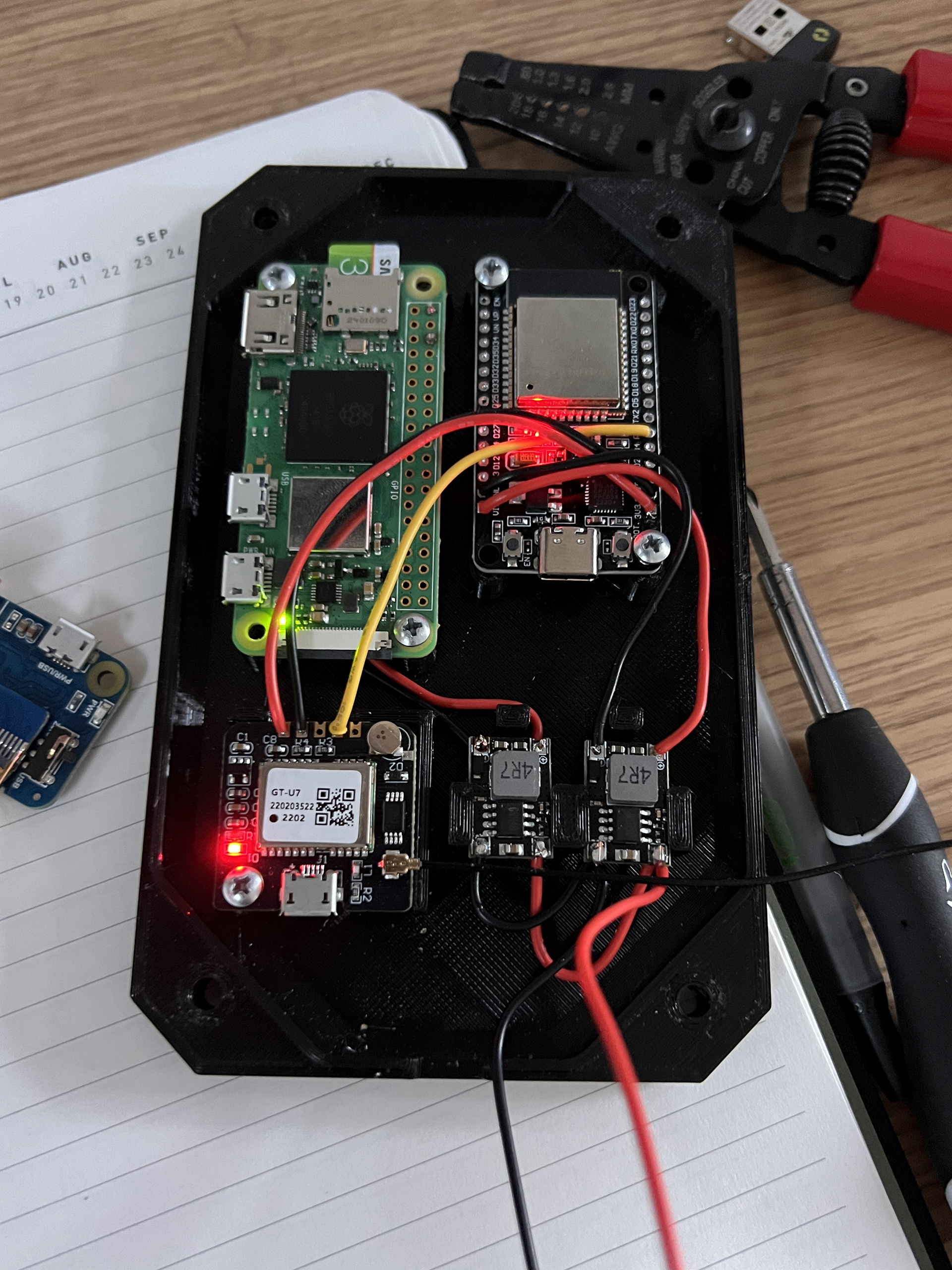
To start learning I decided to get out an ESP32 dev board and start planning a wireless setup where my switches would be inputs on the ESP32, communicating with another ESP32 in the engine bay that controlled by relays for my accessories.
This is where I start to learn about logic level communication and MOSFETS.